
Aquaponiksysteme · Demand-Controlled Loop
Demand-Driven Coupled Aquaponics System
Kontinuierlicher Fisch-Hauptumlauf mit bedarfsabhängig freigegebenem Pflanzenzyklus.
Clearly define operating methods
What is an on-demand coupled aquaponics system?
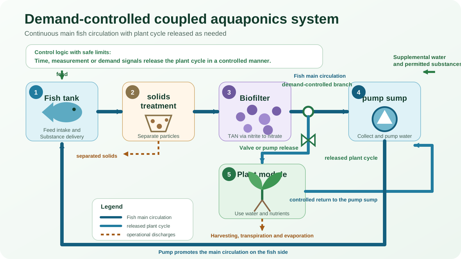
A demand-controlled coupled aquaponics system connects a continuously secured main fish circulation with a plant area, the water supply of which is regulated based on specified time, measurement or demand signals. The water used is then returned to the common water supply.
Coupled
The repatriation remains in effect
Fish and plant areas share water and dissolved substances. The temporal or quantitative regulation of the plant flow does not create an independent plant water cycle.
Demand driven
Approvals follow defined criteria
Irrigation time, water level, substrate moisture, temperature, oxygen supply, culture stage or documented measurements can influence release. A single sensor value does not replace technically defined operating logic.
01
Fish main circulation
Circulation, oxygen supply, solids treatment and biofiltration must function regardless of whether the plant branch is currently active.
02
Regulated plant cycle
Valves or dedicated pumps release the plant flow in a controlled manner. Minimum and maximum running times prevent switching sequences that are too short and undetected continuous delivery.
03
Controlled return
Before re-injection, downtime, temperature, oxygen content and possible substance inputs must be taken into account.
Plan control and hydraulics together
Possible system configurations with demand control
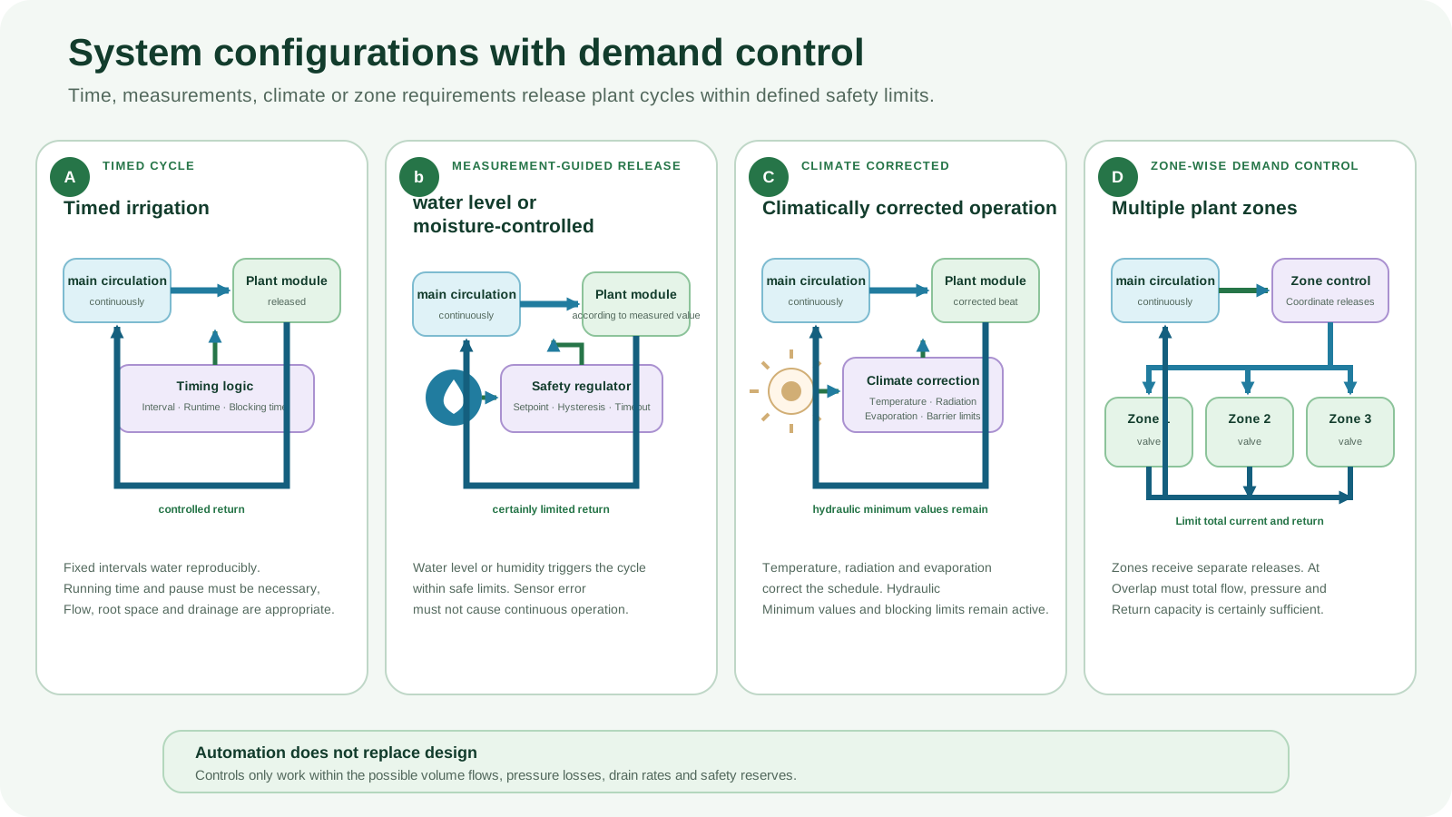
The type of control can vary. What remains mandatory is a viable main fish circuit, a switchable or controllable plant branch and a defined return flow.
A
Timed irrigation
Fixed intervals are only suitable if plant requirements, root space, flow rate and runoff have been tested under real conditions.
b
Water level or humidity controlled
Measured values trigger release within defined safety limits. Sensor errors must not cause unlimited continuous operation.
C
Climatically corrected operation
Temperature, radiation or evaporation conditions can adjust schedules as long as minimum hydraulic conditions are maintained.
D
Multiple plant zones
Separate valves supply zones according to their own needs. Total volume flow, pressure and return capacity must be designed for possible overlaps.
Record volume flow and mass transport separately
Water, solid and nutrient pathway
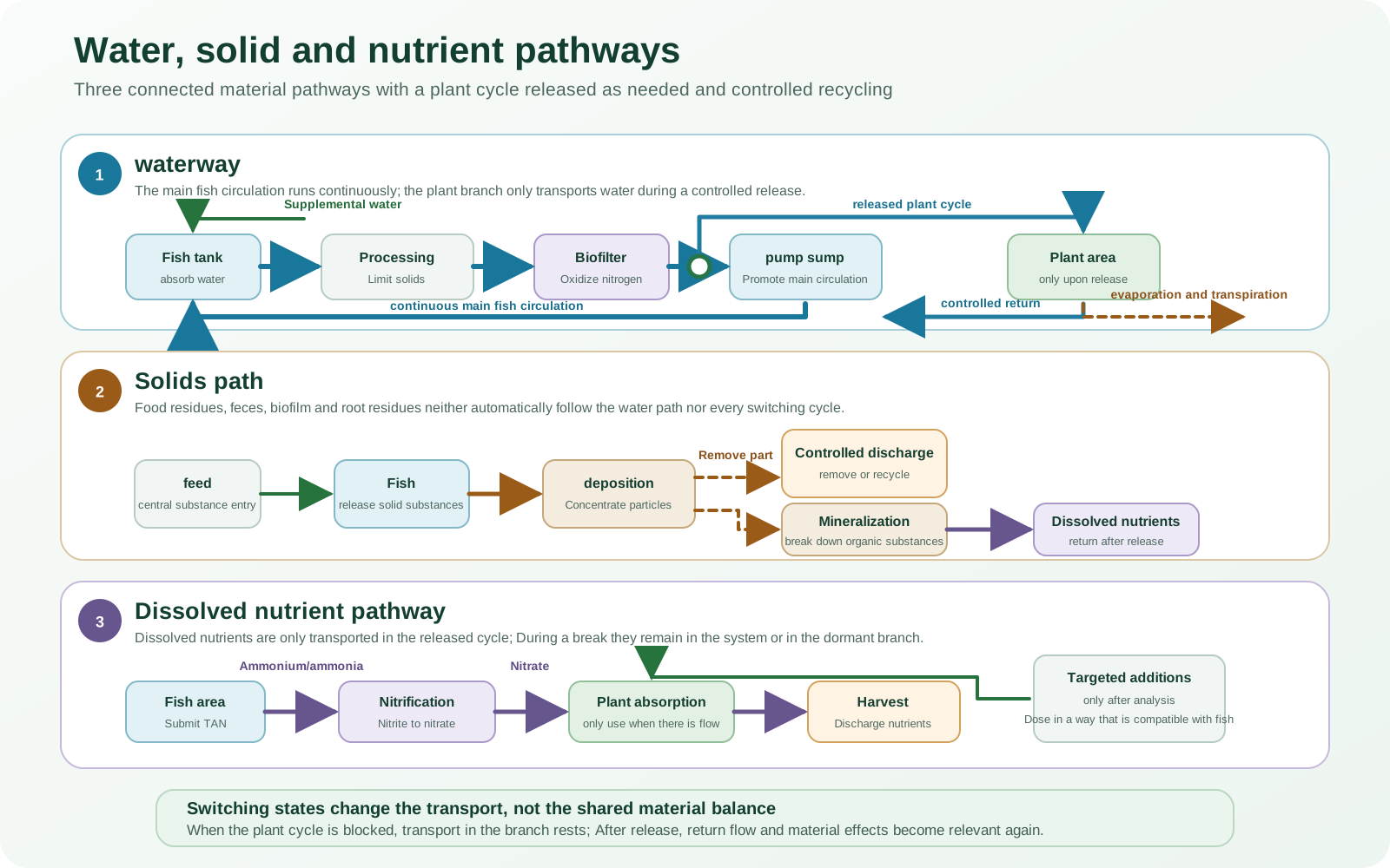
A plant stream that is switched off stops its current water transport. However, dissolved substances remain in the common system or are located in the dormant plant branch.
01
waterway
The main fish circuit circulates continuously. The plant journey begins with a controlled release and ends with the return or a documented discharge.
02
Solids path
Feces, leftover food, biofilm and dead roots do not automatically follow the dissolved water path. Settable solids are limited to sensitive pipes and plant modules.
03
Dissolved nutrient pathway
TAN is biologically oxidized to nitrate via nitrite. Plants only absorb the portion that is reachable and available; Harvesting, flushing and water changes remove substances.
04
Standstill path
In closed strands, temperature, oxygen and microbial activity can differ. This water must not be returned suddenly without assessment.
Permanently secure water treatment on the fish side
Biofilter and nitrification
The biofilter is sized according to the load on the fish and is continuously supplied with water and oxygen. Plant cycles are not a reliable replacement filtration.
Step 1
TAN and NH3-Evaluate share
All ammonia nitrogen includes NH4+ and uncharged NH3. The more toxic NH3-Proportion increases particularly with pH and temperature.
Step 2
Ammonia oxidation forms nitrite
Ammonia-oxidizing microorganisms require suitable surface area, oxygen, water supply and sufficiently stable conditions.
Step 3
Nitrite oxidation forms nitrate
Nitrite oxidizers, including representatives of the genus Nitrospira, oxidize nitrite further. Nitrification consumes oxygen and alkalinity.
Measure biological load, cycle volume and return peak together
Interpretation of feed rate and biological load
The starting point is the maximum realistic daily feed rate. From this, the solids, TAN and oxygen load as well as the required processing and safety reserves are derived.
01
Set production target
Document fish species, stocking, target weight, temperature, feed composition and expected feed intake.
02
Measure the main fish circulation
Solids treatment, biofilters, ventilation and conveying technology must function without active plant branches.
03
Determine cycle volume
Delivery rate and running time result in the volume of water moved per release. Simultaneous zones are included.
04
Check return tip
Collection tanks, overflows and minimum water levels must accommodate the most unfavorable permissible switching state.
05
Set sensor limits
Target, intervention and alarm areas receive hysteresis, plausibility rules and safe substitute values.
06
Validate real operation
Flow, cycle time, return, plant condition and water quality are measured rather than just derived from pump ratings.
Balance flexibility against technical dependency
Operational goal conflicts
Demand control can adjust water movement and energy use, but increases the number and importance of sensors, actuators, switching states and return events.
Less running time – more risk of downtime
Longer breaks save pump running time, but can promote oxygen depletion, heating or deposits.
More zones – more opportunities for error
Individual control improves adaptability, but requires clear valve states and flow control per branch.
Fast response – measurement quality
Automatic interventions are only as reliable as the measuring point, calibration, maintenance and plausibility check.
Stable fish circulation – shared material balance
Hydraulic operational safety does not mean chemical decoupling; Return water continues to affect fish and biofilters.
Demand signal – minimum hydraulics
Plant requirements must not fall below technical minimum flows, flushing requirements or necessary oxygen supply.
Automatic – manual controllability
The system requires understandable manual operation and a documented safe state in the event of a control failure.
Consider feedback with each dosage
Nutrient management and acceptable supplements
Feed remains the central, plannable material input. Demand-controlled water release does not produce a nutrient solution tailored to your needs and does not allow for unrestricted hydroponic dosage.
01
Analyze deficits
Plant symptoms are evaluated along with water or tissue analysis, pH, temperature and alkalinity.
02
Ensure fish compatibility
Supplements must be suitable for fish, biofilters, plants and food production.
03
Document the dosing point
Concentration peaks and the return path are taken into account; Additions are not made uncontrolled into stationary pipes.
04
Treat solids in a controlled manner
Removal or monitored mineralization are accounted for as separate material flows.
05
Specify reference form
Nitrate levels are clearly reported as NO3− or NO3-N denotes; both statements are not identical.
06
Evaluate trends
Intake, feeding, supplementation, harvesting and water changes are considered together over time.
Clearly assign measuring locations and switching states
Water quality and species-specific target areas
A measured value is only meaningful with the measurement location, time, unit, reference form and current switching status.
| group of fish | Temperature orientation | Oxygen orientation | Importance for control |
|---|---|---|---|
| Tilapia and other warm water fish | often around 25–30 °C; Check species, strain and production target | permanently high supply; about 4 mg/l as a lower guide only | Take warm standstill lines and nighttime oxygen consumption into account |
| Carp-like warm to transitional water fish | broad species-specific range; Do not derive production optimum from tolerance | Plan reserves for biomass, feeding and warm periods | Evaluate releases based on actual water temperature |
| Trout-like cold-water fish | often around 12–18 °C; Note type and size class | high demand; usually aim for more than 6 mg/l | Return flow must not cause critical heating or oxygen consumption |
Secure the sensor, actuator and return together
Incidents, biosecurity and redundancy
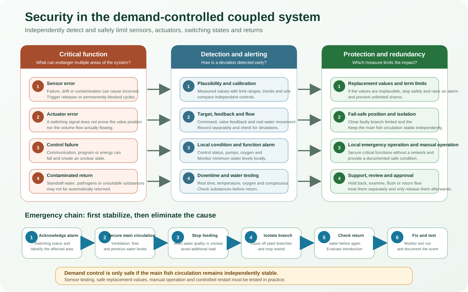
In addition to pump, air and water quality risks, errors arise from implausible measured values, stuck valves, communication failure and incorrect switching sequences.
01
Sensor error
Failure, drift or pollution must not trigger an unlimited plant flow or permanently blocked branch.
02
Actuator error
Valve position and real flow are considered separately; an electrical switching signal does not prove water movement.
03
Control failure
The main fish circulation remains in a locally manageable safe state; critical functions do not depend exclusively on network services.
04
Contaminated return
Unsuitable treatment agents, pathogens or significantly altered stagnant water are not automatically returned.
| Critical function | Early detection | Hedging |
|---|---|---|
| Fish main circulation | Monitor flow, water level, pump status and oxygen | Have emergency ventilation, backup energy, backup pump and safe bypass available |
| Plant cycle | Compare target state, valve feedback and real flow | Limit the running time and make the branch lockable in a controlled manner |
| Return quality | Check downtime, temperature, oxygen and conspicuous substances | Retain, examine, flush or treat return flow separately |
| Biosecurity | Document origin, measures and operational events | Apply quarantine, separate tools and material release |
- Acknowledge alarm and determine affected switching status.
- Maintain fish circulation, ventilation and minimum water levels.
- Temporarily stop feeding if the water quality situation is unclear.
- Isolate faulty plant branches in a controlled manner.
- Check the return water before reintroducing it.
- Eliminate the cause, monitor the test run and document the event.
Only evaluate benefits together with operating expenses
Advantages and limitations
The architecture enables differentiated plant cycles, but remains linked to materials and the return flow.
Possible benefits
- Time- or measurement-dependent supply of different plant zones
- Main fish circulation remains stable during plant breaks
- Cycle volumes and running times can be documented
- Maintenance of individual plant branches is made easier
- Switching states can be alarmed and logged
Limits and additional requirements
- more sensors, valves, pumps and error conditions
- regular calibration and functional testing
- Standstill and return quality must be controlled
- no independent pH, temperature or nutrient control
- Automation requires safe manual operation and emergency operation
Determine control needs before level of automation
Suitability and selection aid
Demand-controlled coupling makes sense when changing plant zones or defined irrigation cycles are operationally justified and can be reliably monitored.
Suitable
For modular plant areas, comprehensible cycle requirements, trained personnel and systems with suitable measurement, alarm and documentation technology.
Only suitable to a limited extent
If the water quality fluctuates significantly, valves are difficult to access, inadequate return control or a lack of maintenance organization.
Do not confuse with decoupling
If the plant area is to manage pH, temperature or nutrient formulation independently and not return water, a truly decoupled architecture is required.
Classify plant modules only in terms of system architecture
Connect to media bed, NFT, DWC and vertical plant modules
The demand control is adapted to the hydraulic properties of the respective plant module. The exact construction and operation method belongs in the later hydroponic system pages.
Media bed
Take filling and emptying cycles, residual water, oxygen entry and solid deposits into account.
NFT
A thin film of water and small root spaces require reliable funding and short, tolerable interruptions.
DWC
Large water volume and ventilation limit the benefit of short switching cycles; Exchange and oxygen supply remain crucial.
Vertical modules
Check the head, uneven distribution, drainage capacity and dryfall risk of each level.
Compare all five system architectures
Does this aquaponics system fit your system?
Compare the water flow, controllability, technical complexity and typical operating conditions of all five system architectures.
Compare all five aquaponics systemsTechnical basis and conceptual boundaries
Specialist sources
The sources cover coupled and decoupled aquaponics, parallel processing, water treatment, nitrification, measurement and control technology. The page title remains a transparently defined project term.
- Somerville, C. et al.: Small-scale aquaponic food production. FAO, 2014.
- Goddek, S. et al.: Navigating towards Decoupled Aquaponic Systems. Water, 2016.
- Tetreault, J.; Fogle, R.L.; Guerdat, T.: Scalable coupled aquaponics design using a parallel unit process approach. 2023.
- Fogarty, S.: Optimizing hydraulic retention times using a parallel unit process approach. 2023.
- Palm, H. W. et al.: Towards commercial aquaponics: systems, designs, scales and nomenclature. 2018.
- Yep, B.; Zheng, Y.: Aquaponic trends and challenges – A review. Aquacultural Engineering, 2019.
- Rakocy, J.E. et al.: Recirculating aquaculture tank production systems: Aquaponics. SRAC Publication No. 454.